Understanding M12 Connector Standards and Coding Types
The M12 connector is the backbone of modern industrial automation, factory instrumentation, and harsh-environment connectivity. Defined globally by the IEC 61076-2-101 standard, this M12 (12mm metric thread) interface ensures mechanical and electrical compatibility across different manufacturers. For design engineers and procurement teams, selecting the correct M12 configuration requires a precise understanding of “coding”—the mechanical keying system that prevents incorrect mating and subsequent electrical shorts or system failures.
To optimize network topology and prevent cross-interface damage, the market relies on several distinct coding standards. Each code is engineered for specific data-rate thresholds, voltage ratings, and industrial protocols:
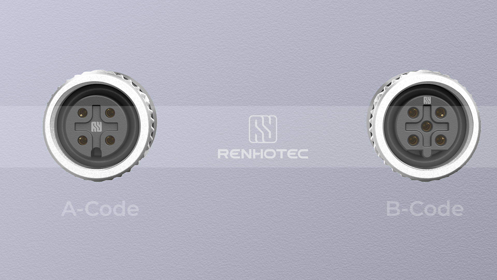
- A-Coded: The most prevalent variant utilized for standard sensor-actuator interfaces, DC power distribution, and basic CAN-bus or DeviceNet architectures.
- B-Coded: Primarily deployed in industrial fieldbus networks, most notably Profibus-DP systems, featuring a reversed keyway to isolate network signals from standard sensor lines.
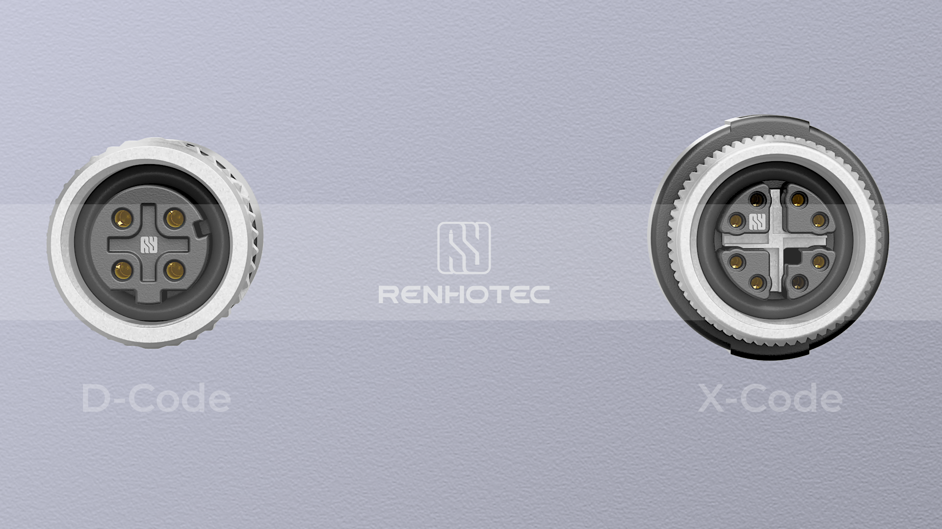
- D-Coded: Engineered specifically for Industrial Ethernet (100Base-TX Fast Ethernet). It features a 4-pin configuration capable of transmitting data up to 100 Mbps.
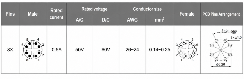
- X-Coded: Developed to meet high-bandwidth requirements in smart manufacturing. It supports Cat6A Industrial Ethernet data rates up to 10 Gbps by isolating its 8 pins into 4 individually shielded pairs.
| Coding Type | Typical Pin Counts | Primary Application Standards | Maximum Data Rate | Voltage / Current Ratings |
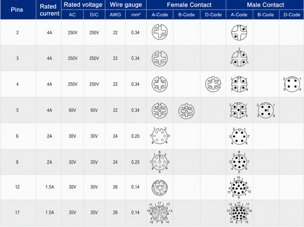
| A-Code | 3, 4, 5, 8, 12 | IO-Link, CANopen, DeviceNet, DC Power | < 100 Mbps | 250V (4-Pin) / 4A |
| B-Code | 3, 4, 5 | Profibus-DP, Interbus | < 12 Mbps | 60V / 4A |
| D-Code | 4 | Industrial Ethernet (100Base-T), Profinet | 100 Mbps | 250V / 4A |
| X-Code | 8 | Cat6A Gigabit Ethernet, Vision Systems | 10 Gbps | 50V AC / 60V DC / 0.5A |
Core M12 Connector Pinout Configurations
Accurate pinout alignment is critical during schematic capture and cabinet wiring. The pin assignment numbering on the mating face of an M12 connector differs between the male (plug) and female (receptacle) variants. The male pin numbering runs clockwise around the center core, whereas the female contact numbering runs counter-clockwise to form a mirrored, perfect-match connection.
A-Coded M12 Pinout (4-Pin, 5-Pin, and 8-Pin)
A-coded variations represent the bulk of sensor footprints. Understanding their physical layouts prevents signal degradation and voltage drops in long cable runs.
- 4-Pin Configurations: Standardized for basic proximity switches and photoelectric sensors operating on 24V DC loops.
- 5-Pin Configurations: Frequently used where a functional earth (FE) or a secondary complementary signal output is mandatory.
- 8-Pin Configurations: Deployed in high-density I/O blocks, multi-channel analog sensors, and specialized incremental encoders.
D-Coded and X-Coded M12 Pinout for Industrial Ethernet
In industrial networking, signal integrity is compromised by Electromagnetic Interference (EMI) generated by adjacent motors and VFDs. Choosing and pinning the correct Ethernet variant is paramount.
- D-Coded Matrix: Employs 4 pins mapped to receive and transmit pairs (Tx+, Tx-, Rx+, Rx-). It is fully optimized for standard 4-wire Ethernet cables running Profinet or EtherCAT protocols.
- X-Coded Matrix: Arranges 8 pins within a cross-shaped internal metallic shield. This specialized shield prevents internal near-end crosstalk (NEXT) between the differential pairs, allowing it to easily clear IEEE 802.3an 10GBASE-T testing thresholds.
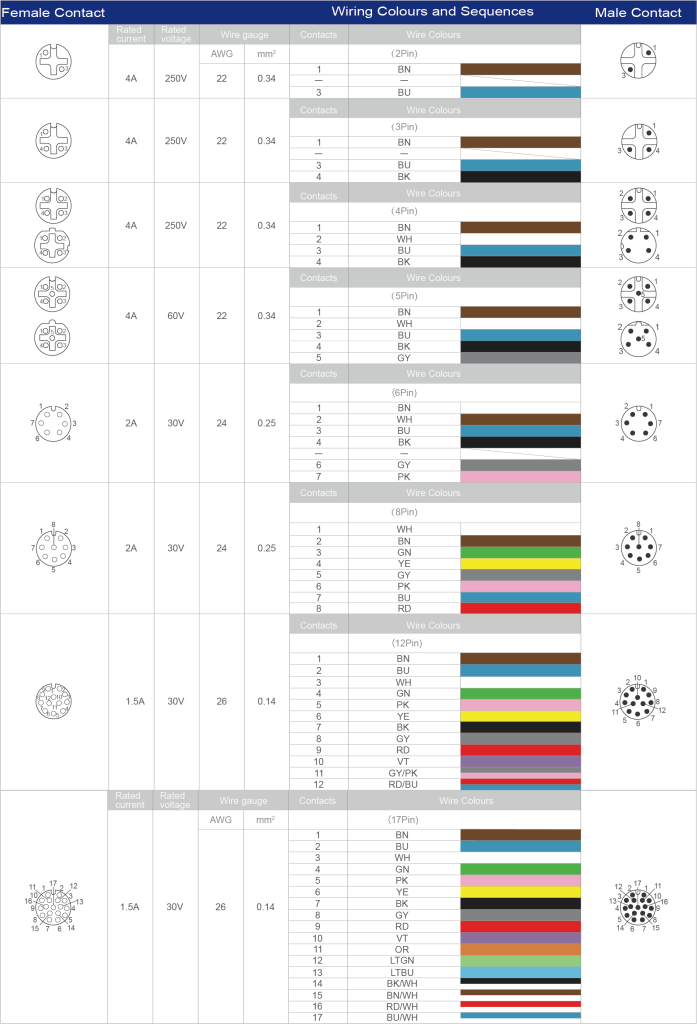
M12 Connector Color Code and Wiring Standards
Implementing error-free terminations during field deployment or serial cable assembly requires strict adherence to color-coding standards. For industrial automation, the dominant reference is IEC 60947-5-2, which standardizes the wire color mapping for sensor and actuator loops to guarantee cross-brand interoperability. Deviating from these color assignments leads to critical faults, such as reverse polarity damage to sensitive PNP/NPN sensor outputs or communication time-outs on industrial bus networks.
Standard Low-Pin M12 Wiring Conventions
Low-pin configurations represent the foundational standard for power loops and digital/analog switching signals. The standardized wire colors map directly to specific electrical parameters:
- 3-Pin Configurations: Primarily used for basic 2-wire or 3-wire DC sensors. Pin 1 (Brown) carries +24V DC, Pin 3 (Blue) serves as 0V GND, and Pin 4 (Black) acts as the primary switching output (OUT).
- 4-Pin Configurations (m12 connector 4 pin wiring): Adds Pin 2 (White), which operates as a secondary complementary signal output or a digital input channel (I/O).
- 5-Pin Configurations: Introduces Pin 5 (typically Grey, or Green/Yellow in specialized power layouts), which is frequently utilized as a functional earth (FE) ground or a dedicated shielding line to mitigate low-frequency electrical noise.
High-Density M12 Wiring Conventions
As signal density inside automated machinery increases, migrating to an 8-pin, 12-pin, or 17-pin m12 cable pinout becomes necessary. These high-density arrays integrate power, multi-channel analog telemetry, and communication bus lines into a single shielded jacket.
How the M12 X-Code Field Installable Connector Works & Step-by-Step Installation Tutorial
In modern smart factories and high-throughput material handling environments, deploying pre-molded cables is not always feasible due to variable structural routing paths. This is where M12 Field Wireable Connectors become essential. Specifically, understanding how the M12 X-code field installable connector works clarifies why it can maintain Cat6A Gigabit performance even when terminated directly on the factory floor without specialized machinery.
Internal Mechanisms of the X-Code Field Installable System
The core engineering challenge for an 8-pin high-frequency connector is managing Near-End Crosstalk (NEXT) and Return Loss (RL) at frequencies up to 500 MHz. The X-coded field installable architecture resolves this via a specialized internal cross-shaped metallic shield (X-shield).
When a multi-pair Ethernet cable is terminated inside the housing, this X-shield physically isolates the four differential signal pairs (DA, DB, DC, DD) into four separate quadrants. Concurrently, advanced field-wireable models utilize IDC (Insulation Displacement Contact) technology or mini-PCB solderless terminals. When the connector housing is threaded together, it forces the insulated wires into sharp V-shaped contact slots, slicing through the outer PVC/PUR jacket to form a gas-tight, vibration-proof electrical connection without degrading the shield’s continuity.
Step-by-Step M12 Field-Wireable Installation and Stripping Tutorial
To ensure an IP67 liquid-tight seal and prevent short circuits between tightly packed terminals, follow this precise mechanical sequence based on your specific hardware footprint:
- Step 1: Component Threading Sequence
Slide the components onto the raw cable in the exact sequence shown in your hardware profile: first the rear metal housing with integrated sealing rubber gland, followed by the 360° metal shielding/clamping ring. Warning: Forgetting to thread these components before stripping forces complete re-work.
- Step 2: Cable Jacket Stripping
Strip back the outer PVC/PUR cable jacket by 20mm using an industrial jacket stripper. Carefully fold the exposed braided wire shield backward over the cable jacket.
- Step 3: Core Insulation Stripping (Crucial Change)
Unlike IDC connectors, you must strip the individual insulation of each colored core wire by exactly 4mm to 5mm, exposing the bare stranded copper threads. Twist the copper strands tightly to prevent stray wires from shorting adjacent terminals.
- Step 4: Pin Mapping and Screw Termination
Loosen the mini-screws on the connector core insert. Insert each bare copper wire into its designated terminal hole following your specific standard m12 wiring diagram (e.g., Pin 1 = Brown, Pin 3 = Blue). Use a precision 1.5mm flathead screwdriver to tighten each screw firmly onto the bare copper wire.
- Step 5: Shielding Engagement
Push the 360° metal shielding/clamping ring forward so it firmly grips the folded-back braided wire shield. This guarantees absolute EMI/RFI protection across the entire enclosure loop.
- Step 6: Final Housing Interlock
Thread the front contact carrier core into the rear metal housing. Tighten the assembly until the internal rubber sealing gland compresses fully around the cable jacket. Apply a final locking torque of 1.0 Nm to prevent loosening from machine vibrations.
Professional M12 Connector Selection Guide: Custom Capabilities and Supply Chain Support
Selecting the ideal M12 mechanical footprint involves balancing application-specific electrical demands with environmental constraints. Specifying incorrect housing geometries or contact methodologies often causes physical interference during system integration or accelerated dielectric breakdown under high vibration.
Choosing Between Molding Cables, Panel Mount, and Splitters
To ensure long-term durability on the factory floor, hardware designers must categorize M12 hardware into defined mechanical segments:
- M12 Molding Cables: Best suited for standard, repetitive wiring paths where factory-sealed IP67/IP68 protection is mandatory. Overmolded polyurethane (PUR) or polyvinyl chloride (PVC) jackets encapsulate the cable-to-connector transition, providing superior strain relief and preventing the ingress of water, cutting oils, or chemical solvents.
- M12 Panel Mount Connectors: These serve as the critical interface between internal PCBs and external industrial networks. Available in front-mount or rear-mount threaded configurations with solder cups, PCB pins, or flying leads, they provide robust IP67 sealing directly on control cabinets and sensor housings.
- M12 Splitters / Adapters: Essential for optimizing network topologies. T-shaped or Y-shaped splitters combine two distinct sensor signals into a single 4-pin or 5-pin master cable, significantly reducing cable routing costs and simplifying I/O distribution block layouts.
Internal Laboratory Verification
Our M12 interconnect solutions are engineered to meet or exceed OEM mechanical and electrical specifications, providing seamless drop-in alternatives for existing bills of materials (BOMs). To accelerate procurement verification cycles, our internal laboratory conducts rigorous performance qualification testing:
- Environmental Survivability: Extended salt-spray exposure testing (up to 96 hours) verifies plating integrity, while thermal shock cycles validate sealing performance from -40°C to +85°C.
- Mechanical Integrity: Automated mate/unmate endurance testing ensures gold-plated contacts sustain a minimum of 500 mating cycles without localized resistance spikes.
- Electrical Verification: Dielectric withstanding voltage tests check for insulation breakdown up to 1500V AC, ensuring complete transient safety under heavy industrial loads.

Request an M12 Connector Quote or Download Datasheets
Optimizing industrial connectivity requires component reliability and precise engineering support. Whether you need to replace single OEM part numbers, source specialized M12 Panel Mount Connectors, M12 Field Wireable Connectors or configure customized M12 Molding Cables, our engineering team can provide detailed layout drawings, custom electrical schematics, and rapid prototype samples.
Frequently Asked Questions (FAQ)
Can I mate an A-coded plug into a B-coded receptacle?
Answer: No. M12 connectors feature strict mechanical keying to enforce physical error-proofing (poka-yoke). The physical profiles of the internal alignment tabs and keyways differ entirely across coding variants. Attempting to force cross-mating will permanently deform the internal copper pins or crack the plastic contact carrier, resulting in insulation failure or open circuits.
What is the operational difference between IP67 and IP68 ratings for M12 connectors?
Answer: An IP67 rating ensures the connector is completely dust-tight and can withstand temporary immersion in water up to 1 meter for 30 minutes. An IP68 rating indicates suitability for continuous immersion under pressure—typically down to 1.5 or 3 meters for 24 hours. Our premium overmolded and panel-mount interfaces are rated to meet IP68 criteria, making them highly reliable for washdown environments.
Why is X-coded recommended over D-coded for new industrial network designs?
Answer: D-coded connectors are limited to 4 pins and a maximum data rate of 100 Mbps (Fast Ethernet). X-coded interfaces utilize 8 pins separated by an internal cross-shield, allowing them to support Cat6A Gigabit Ethernet speeds up to 10 Gbps. For future-proof architectures involving high-resolution vision systems, edge computing, or dense I/O telemetry, X-coded is the industry standard.
Are these M12 connectors fully compliant with environmental regulations like RoHS and REACH?
Answer: Yes, all our M12 components, including the copper alloy pins, zinc alloy hex nuts, and PUR jackets, strictly adhere to EU RoHS (Restriction of Hazardous Substances) and REACH compliance frameworks. Materials are verified to contain less than the mandated thresholds of heavy metals and hazardous flame retardants, ensuring global export compliance for your finished equipment.
Why is X-coded recommended over D-coded for new industrial network designs?
Answer: D-coded connectors are limited to 4 pins and a maximum data rate of 100 Mbps (Fast Ethernet). X-coded interfaces utilize 8 pins separated by an internal cross-shield, allowing them to support Cat6A Gigabit Ethernet speeds up to 10 Gbps. For future-proof architectures involving high-resolution vision systems, edge computing, or dense I/O telemetry, X-coded is the industry standard.
How do I choose between PVC and PUR cable jackets for M12 assemblies?
Answer: PVC is a cost-effective material best suited for static applications with low mechanical stress and moderate exposure to moisture. PUR (Polyurethane) is a high-performance material optimized for dynamic applications like drag chains or robotic arms. It offers exceptional resistance to abrasion, continuous flexing, micro-organisms, and aggressive cutting oils common in CNC machining.

As a Product Manager at Renhotec Group (est. 2008), I specialize in providing deep technical insights into connectors, cables, and custom electronic components. Renhotec is a global leader in interconnect solutions, dedicated to manufacturing high-standard products for diverse industries as your trusted technical partner.