Architecture of Industrial Camera Cable Assemblies: Mechanical and Electrical Specifications
Industrial camera cable assemblies are fundamental yet highly critical points of failure in automated imaging systems. Unlike consumer-grade peripheral cabling, machine vision cables operate under sustained structural stress, continuous mechanical articulation, and high-frequency electromagnetic interference (EMI). To maintain uncorrupted packet delivery and zero-latency signal processing from sensor to frame grabber, precision component matching and robust structural layer design are required.
The underlying mechanical durability and signal fidelity of a professional-grade cable are governed by its multilayer cross-sectional architecture:
- Conductor Composition: High-flexibility cable configurations utilize ultra-fine stranded Oxygen-Free Copper (OFC) cores, typically rated between 26 AWG and 28 AWG for data lines. Fine stranding prevents micro-fractures within the copper crystal matrix during high-frequency cyclic bending.
- Dielectric Insulation: Advanced compounds like Fluorinated Ethylene Propylene (FEP) or specialized Polyethylene (PE) provide low dielectric constants. This minimizes parasitic capacitance, optimizing propagation velocity for high-bandwidth protocol signaling.
- Shielding Architecture: Industrial camera cables integrate a dual-layer shielding topology combining a 100% coverage Aluminum-Mylar foil wrap with a high-density (>85% optical coverage) tinned copper braided mesh. This dual mechanism attenuates high-frequency radiated EMI and low-frequency inductive noise common in factory floors populated by heavy servo drives and variable frequency monitors.
- Outer Jacket Formulations: Thermoplastic Polyurethane (PUR) or oil-resistant Polyvinyl Chloride (PVC) jackets protect the internal shielding elements. PUR jackets offer excellent tear resistance, hydrolysis stability, and endurance against abrasive sliding actions within industrial cable drag chains.
In high-speed imaging setups, Controlled Impedance (100Ω±5Ω for differential signaling paths) and low Insertion Loss (Signal Attenuation) are essential performance metrics. When impedance discontinuities manifest due to physical cable degradation or sub-par assembly tolerances, RF signal reflections occur. These reflections manifest as a high Bit Error Rate (BER), causing dropped frames, pixel artifacts, or total communication handshake termination between the camera and the host system.
| Cable Layer Parameter | Specification Standard | Technical Importance in Machine Vision |
|---|---|---|
| Conductor Material | Stranded Oxygen-Free Copper (OFC) | Minimizes conductor fatigue and prevents micro-cracking during dynamic motion. |
| Shielding Performance | Al-Mylar Foil + >85% Tinned Copper Braid | Suppresses EMI/RFI from nearby high-voltage lines, preventing packet loss. |
| Differential Impedance | 100Ω±5Ω (Protocol Dependent) | Matches transmission line impedance to eliminate signal reflections and jitter. |
| Jacket Compound | High-Flex PUR or Industrial Grade PVC | Resists industrial cutting oils, chemical exposure, and mechanical wear. |
Decoupling Camera Interface Cables: Protocol Standards and Hardware Selection
Selecting the correct camera interface cables requires balancing bandwidth, distance, and environmental resilience. Machine vision protocols vary in performance. Choosing an incompatible assembly can cause bottlenecked data rates or physical port damage. Below, we break down the three primary digital camera standards used in factory automation.
GigE Cables: Long-Distance Transmission and PoE Optimization
GigE Vision remains the industry standard for long-distance machine vision networks. Standard GigE cables can reliably transmit data up to 100 meters without intermediate signal repeaters, making them ideal for large-scale multi-camera inspection cells. For industrial deployments, standard RJ45 connectors are upgraded to include integrated locking screws (gige rj45 screw configurations) or robust M12 X-Coded 8-pin circular connectors to eliminate decoupling under continuous physical vibration.
Power over Ethernet (PoE) allows a single network cable to simultaneously conduct high-speed data transmission and deliver up to 15.4W (IEEE 802.3af) or 30W (IEEE 802.3at) of DC power to the camera. This dual functionality presents thermal challenges. When multi-core network lines are grouped in narrow wire trays, high electrical resistance in narrow-gauge conductors induces localized thermal spikes. To mitigate this insertion loss and prevent inner dielectric core deformation, we specify 24 AWG or 26 AWG pure copper conductor pairs enclosed in individual foil wraps with an overall tinned copper braid (SFTP construction).
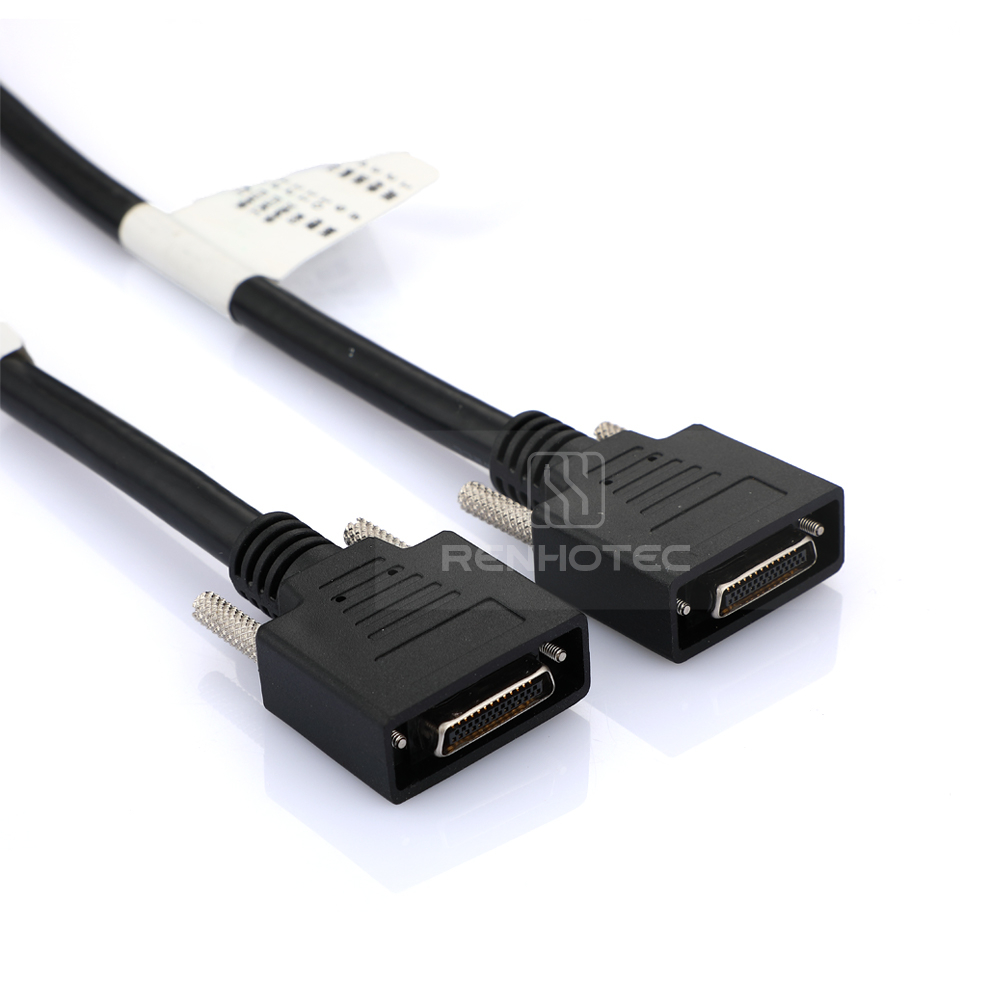
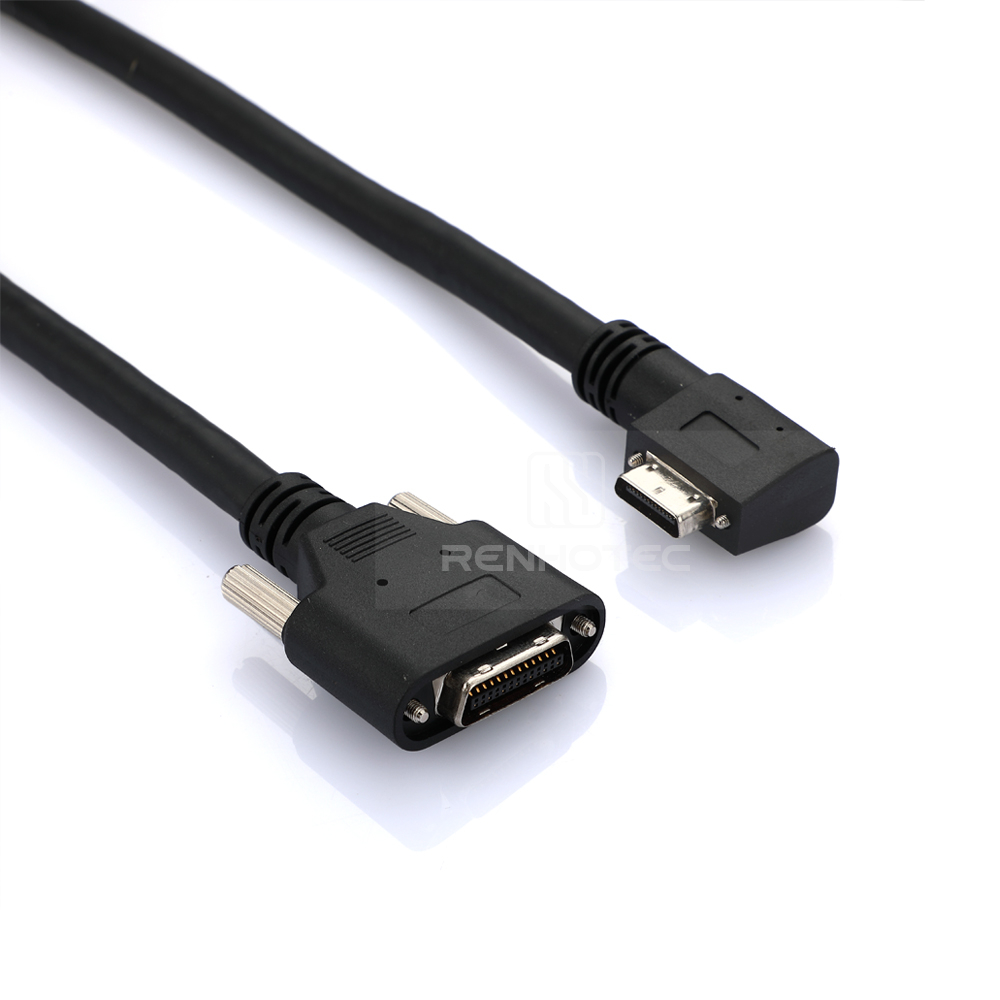
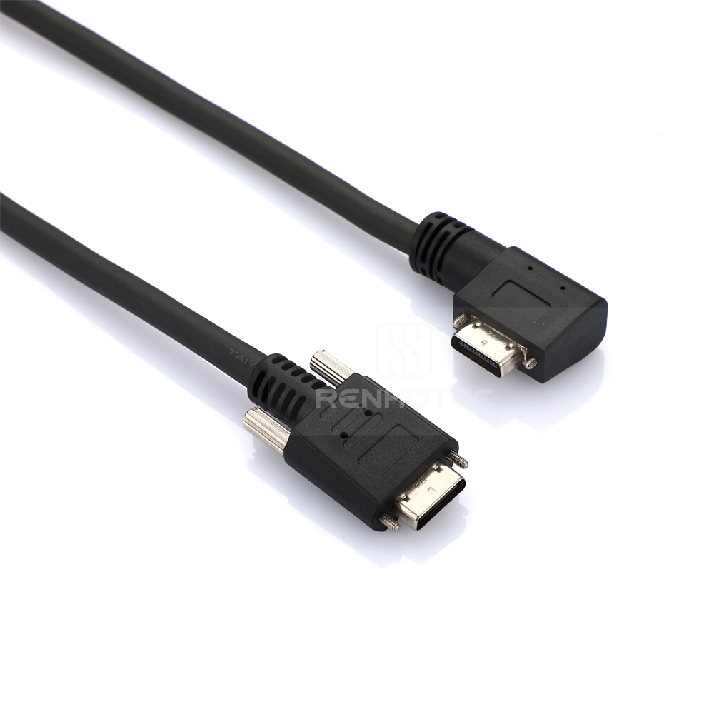
Camera Link Cables: MDR vs. SDR Form Factors and PoCL Compliance
For applications requiring high raw bandwidth and deterministic real-time processing with zero host CPU overhead, the Camera Link cable is standard. The protocol requires dedicated parallel-to-serial topologies, operating via two primary physical connection profiles: the larger 26-pin mdr cable (Mini Delta Ribbon) and the compact 26-pin sdr connector (Shrunk Delta Ribbon).
Depending on the image resolution and required frame rate, the transmission network is configured into three distinct tiers:
- Base Configuration: Uses a single 26-pin cable providing up to 2.04 Gbps video bandwidth.
- Medium/Full Configuration: Requires dual mdr & sdr cable assemblies running in parallel to unlock up to 5.44 Gbps data throughput.
- Extended Full Configuration: Pushes the physical architecture up to 6.8 Gbps via specialized 80-bit mapping configurations.
Modern vision systems utilize Power over Camera Link (PoCL). This development supplies electrical power directly through the standard data pin assignments, eliminating the need for separate external power cords. When using PoCL, strict line impedance matching (100Ω±10%) is mandatory. Minor physical structural deviations within the cable core can trigger voltage cross-talk or high current surges, leading to component failure on the frame grabber card.
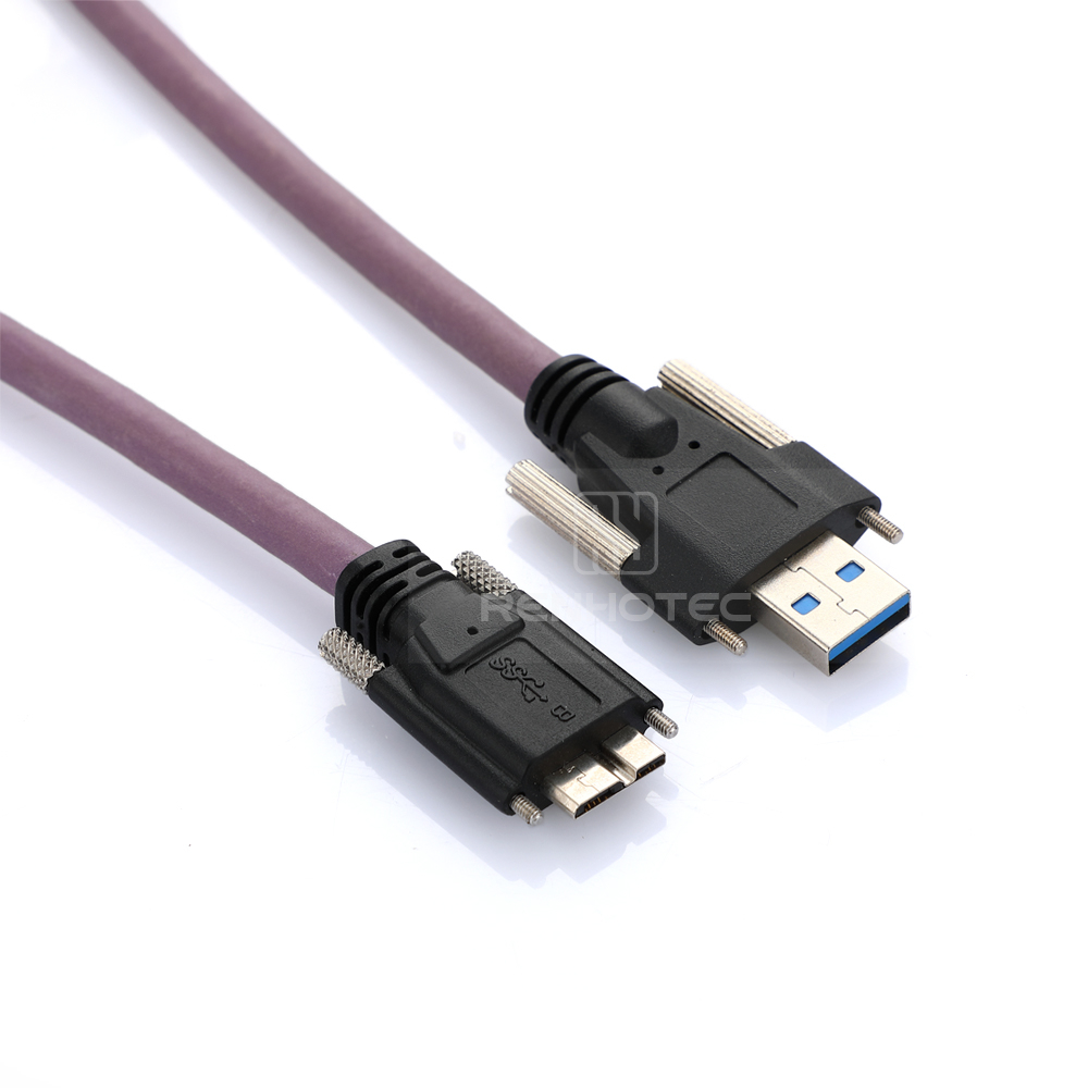
USB Camera Cables: USB 3.0 Micro-B and Type-C for High-Bandwidth Machine Vision
The USB3 Vision framework provides plug-and-play operation and high transmission bandwidth, delivering up to 5 Gbps for USB 3.0 and up to 10 Gbps for USB 3.1 Gen 2 architectures. However, copper-based USB camera cables have a notable drawback: physical transmission distance is typically limited to a maximum of 4.5 meters before severe signal attenuation corrupts high-speed data packets.
To make USB stable for factory automation environments, two critical enhancements are used:
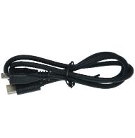
- Mechanical Thread Locking: Standard friction-fit ports are replaced by industrial connectors featuring a secure micro usb-b port lock or rigid dual-screw locking USB Type-C housings. This hardware modification prevents erratic signal drops caused by the high acceleration of robotic gantry axes.
- Active Optoelectronic Extenders: For cable runs exceeding 5 meters, Active Optical Cables (AOC) are deployed. These hybrid assemblies feature miniature electrical-to-optical conversion chipsets integrated within the connector shells, enabling lossless 5 Gbps data transmission across distances up to 30 meters with absolute resistance to electromagnetic interference.
Machine Vision Interface Reference Table
| Protocol Interface | Core Cable Keyword | Maximum Copper Length | Standard Connector Profiles | Power Delivery Mechanism |
| GigE Vision | GigE Cables | 100 Meters | RJ45 with Locking Screws, M12 X-Coded | Power over Ethernet (PoE) |
| Camera Link | Camera Link Cable | 10 Meters | MDR 26-Pin, SDR (Mini) 26-Pin | Power over Camera Link (PoCL) |
| USB 3.0 Vision | USB3 Camera Cable | 4.5 Meters | Micro USB-B with Dual Lock, Type-C | USB Bus Powered (VBUS 5V) |
Industrial Power I/O Cables: Triggering and Synchronization Mechanics
While high-speed data transmission is critical, a machine vision system cannot function without precise timing and power management. This is the role of industrial Power I/O Cables. These assemblies do more than just deliver DC voltage to the camera; they carry high-speed General Purpose Input/Output (GPIO) signals. These signals synchronize the camera’s shutter with hardware components like external LED strobes, laser line profilers, or proximity sensors on a conveyor belt.
To prevent electrical noise from corrupting data or damaging sensitive sensor electronics, industrial cameras use opto-isolated I/O channels. The cable assembly must maintain isolation across these channels. For example, a standard hirose trigger cable utilizes specialized twisted-pair internal wiring configurations. This configuration separates the primary power lines (+12V or +24V DC) from the sensitive, low-voltage trigger lines (5V TTL or 24V PLC logic). This shielding approach prevents cross-talk, ensuring sub-microsecond synchronization accuracy for high-speed automated sorting applications.
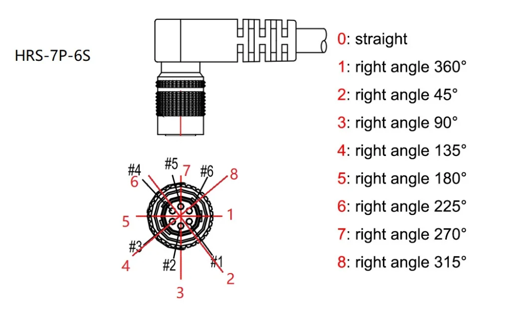
The industry standard for these interfaces relies heavily on Hirose miniature circular connectors. This includes the push-pull HR10A series and the high-density screw-lock HR25 series. Selecting the right pin configuration and connector type is essential for proper system integration:
- 6-Pin Interconnects: A common choice for standard cameras (such as the Basler ace series), a 6 pin hirose female cable provides lines for power ground, DC power input, one opto-isolated input, and one opto-isolated output.
- 8-Pin configurations: Frequently specified for multi-I/O configurations like the Hikrobot 8-pin Trigger Cable. These provide additional lines for non-isolated configurable GPIO channels.
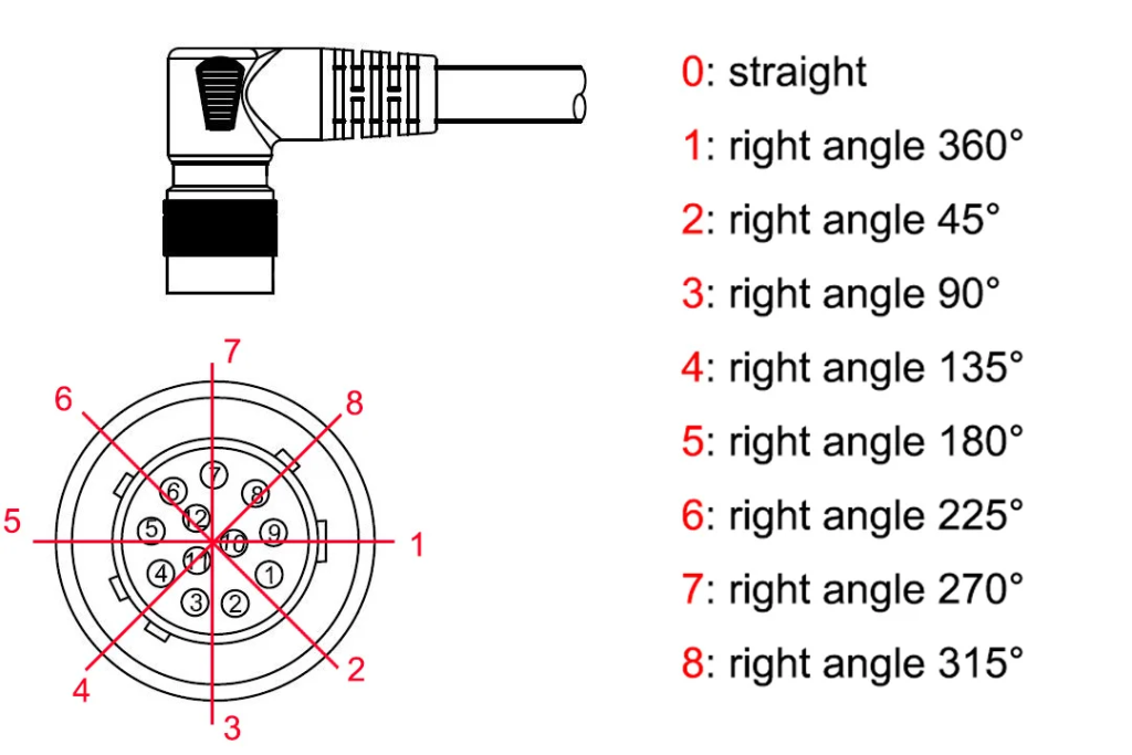
- 12-Pin High-Density Interfaces: Used in high-performance cameras, these match assemblies like the hirose hr10a 7p 12p matrix. They support complex multi-strobe triggers, quadrature encoder inputs for line-scan applications, and dual-voltage power rails.
Industrial environments expose these cables to mechanical stress and harsh chemicals. Wire trays often contain cutting oils, chemical coolants, and moisture. Standard cable insulation can degrade under these conditions, leading to short circuits. To prevent this, professional Industrial Camera Power Trigger IO cables are manufactured with specialized Polyurethane (PUR) or oil-resistant Polyvinyl Chloride (PVC) outer jackets. These jackets maintain their physical integrity and shielding performance even under continuous exposure to common industrial fluids.
| Pin Configuration | Core Keyword Reference | Core Interconnect Model | Target Application Profile |
| 4-Pin Circular | 4 Pin Hirose Cable | Hirose HR10A-7P-4S | Basic DC power supply with no external hardware triggering. |
| 6-Pin Circular | 6 pin hirose female cable | Hirose HR10A-7P-6S | Standard single-frame trigger input with one strobe output line. |
| 8-Pin Circular | hirose 8 pin cable | Hirose HR25-7TP-8S | Multi-I/O synchronization with integrated PLC logic line setups. |
| 12-Pin Circular | 12pin hirose cable | Hirose HR10A-10R-12S | Line-scan cameras requiring direct quadrature encoder connection. |
Selection Guide: How to Choose the Right Industrial Camera Cable
Sourcing the correct interconnect solution requires a systematic analysis of both electrical requirements and physical deployment constraints. Selecting an incorrect line specification often leads to premature mechanical failures or data packet dropouts. To help system integrators and procurement departments mitigate these risks, our engineering team has developed a four-tiered matrix framework to simplify the evaluation process.
The evaluation process follows a structured engineering workflow:
- Bandwidth and Protocol Allocation: Determine the raw data output of the selected imaging sensor. High-resolution, high-frame-rate sensors require the parallel architecture of a Camera Link Cable or the high-throughput capabilities of a USB3 Camera Cable. For multi-camera networks that handle lower individual bandwidth, a unified network switch utilizing standard GigE Cables is the industry standard approach.
- Distance vs. Attenuation Boundaries: Map the actual layout of the factory floor. If the distance between the optical inspection station and the host industrial PC (IPC) exceeds 5 meters, passive USB options become unreliable due to signal loss. For these layouts, engineers must choose between 100-meter copper gige cables or implement active optoelectronic extenders for high-bandwidth interfaces.
- Kinematic Profiling: Evaluate the physical movement profile of the installation path. For fixed, stationary installations, standard static-rated assemblies are sufficient. However, if the cable must guide signals inside a continuous multi-axis drag chain or on a robotic arm, a specialized high-flex machine vision cable is mandatory to prevent internal conductor fatigue.
- Spatial and Orientation Constraints: Analyze the clearance space directly behind the camera enclosure. In compact machinery setups or shallow electrical cabinets, standard straight connectors can exceed the available space or force sharp bends that damage internal shielding. For these tight footprints, specifying right-angle, left-angle, up-exit, or down-exit connector housings keeps the bend radius within safe limits.
Mitigating Failure Modes in High-Flex Machine Vision Cable Applications (Sourcing-Friendly Edition)
Deploying Industrial Camera Cables within automated, moving machinery exposes the wire to continuous physical stress. Standard interconnect lines, when forced into high-acceleration reciprocating movements, quickly experience structural failures. Understanding why these lines fail helps procurement managers and distributors assist customers in selecting the correct specification, reducing product returns, and enhancing technical authority.
Mechanical fatigue typically manifests through three common degradation pathways:
- Conductor Fatigue (Internal Wire Snaps): Under continuous bending, individual internal copper strands become brittle and snap. This creates intermittent connections that are difficult to diagnose. The system works perfectly fine when stationary but drops frames or throws errors the moment the production line accelerates. This hidden failure is usually due to using standard wire instead of a specialized high-flex machine vision cable.
- Shielding Degradation (Video Noise and Artifacts): Continuous twisting and bending can tear the internal Aluminum-Mylar foil and break the tinned copper braid. Once this shield fails, external electrical noise from nearby high-voltage lines or servo motors leaks into the line, resulting in horizontal lines, image distortion, or sudden black screens.
- Outer Jacket Wear (Physical Abrasion): In high-speed drag chains, cables continuously rub against each other and the chain walls. If the jacket material lacks sufficient abrasion resistance, it will wear through, exposing the internal metallic shielding to dust, cutting oils, and moisture, which risks causing electrical short circuits.
To prevent premature wire wear and avoid customer complaints, buyers should verify two critical parameters during selection:
- Verify the Safe Bend Radius: Wires must not be bent at sharp angles. For dynamic moving configurations, the minimum bend radius (R) should be calculated using the cable’s overall outer diameter (OD) as a baseline guide:
R ≥ 10 × OD (For Standard Dynamic Moving Configurations)
- Specify the Right Jacket Compound: If the factory floor exposes cabling to cutting oils, chemical coolants, or moisture, avoid standard plastic compounds. Specify an extruded Polyurethane (PUR) outer jacket wrapper for maximum wear and oil resistance. Additionally, utilize secure connectors with manual locking hardware (such as a micro usb-b port lock) to eliminate connection drops caused by continuous machine vibration.
Cross-Reference & Procurement Guide: Sourcing High-Performance Alternatives
Our engineering team maintains an extensive database of cross-reference alternatives that match the exact physical and electrical profiles of major global vision brands. Whether your bill of materials (BOM) specifies components for Basler GigE networks, Cognex sensor linkages, FLIR cameras, or Hikrobot manufacturing lines, our replacement options provide a direct fit. They match the original housing profiles, thread specifications, pin configurations, and shielding metrics to ensure seamless deployment.
Every assembly undergoes strict testing in our quality assurance laboratory to ensure long-term reliability. We use advanced high-frequency network analyzers to verify characteristic impedance and insertion loss across differential signaling lines. Additionally, our multi-axis drag chain simulation systems subject sample lots to continuous multi-million cycle flex testing, verifying conductor durability before bulk shipping.
For specialized industrial machinery layouts, we provide full custom assembly manufacturing services. Beyond standard straight interconnect lines, our engineering team builds custom configurations tailored to your specific application needs:
- Custom lengths: Built to your exact layout dimensions to eliminate extra wire slack in narrow enclosures.
- Angled connector orientations: Configured in up, down, right, or left-exit configurations to simplify routing in tight spaces.
- Specialized jacket compounds: Selected to handle extreme factory environments, including oil immersion, high temperatures, or continuous twisting motion.
- Hybrid multi-leg branch wire bundles: Combines power, data transmission, and external triggering lines into a single, clean cable jacket to simplify system installation.
| OEM Target Reference Brand | Target Product Application Group | Replacement Cable Identifier | Validated Core Technical Metric |
| Basler ace / dart | Power Delivery and Hardware Sync | basler camera io cable | 6-Pin Hirose layout with pure copper lines. |
| Cognex In-Sight | Vision Sensor Data and Power Link | Cognex Compatible I/O Cable | Integrated M12 X-Coded to RJ45 shielding. |
| FLIR Blackfly | High-Frame-Rate Capture Setup | USB3 Camera Cable | Double locking screws to prevent data drops. |
| Hikrobot MV Series | Dynamic Manufacturing Cells | Hikrobot 8-pin Trigger Cable | High-flex PUR jacket with 10M cycle rating. |
Industrial camera cables are the high-frequency neural conduits that determine the speed, accuracy, and overall lifespan of machine vision systems. Whether your application requires the 100-meter range of GigE Cables, the massive bandwidth of a USB3 Camera Cable, or the real-time execution of a Camera Link Cable, choosing the correct physical shielding, proper jacket composition (such as PUR), and secure locking mechanics is essential to prevent line fatigue and costly machine downtime. Partner with Renhotec today to optimize your interconnect supply chain—contact our sourcing desk to request technical datasheets, apply for free high-flex test samples, or get a custom quote tailored to your engineering drawings.

As a Product Manager at Renhotec Group (est. 2008), I specialize in providing deep technical insights into connectors, cables, and custom electronic components. Renhotec is a global leader in interconnect solutions, dedicated to manufacturing high-standard products for diverse industries as your trusted technical partner.