NMEA 2000 is the standard protocol for communication between marine electronic devices, widely used in navigation, monitoring, and control systems. To understand how to set up and maintain an NMEA 2000 network, it is crucial to know the differences between backbone cables and drop cables. The main differences between NMEA 2000 backbone cables and drop cables lie in their functions, lengths, and roles in the network structure. Below is a detailed comparison:
Quick Comparison: Backbone vs. Drop Cable
| Aspect | Backbone Cables | Drop Cables |
| Function | Main communication pathway of the network | Connect individual devices to the backbone |
| Maximum Length | 200 meters (656 feet) | 6 meters (20 feet) |
| Usage | Connects T-connectors along the boat, forming the network structure | Runs from T-connectors to individual devices |
| Network Structure | Backbone cables act as the central spine of the network, running along the boat and connecting various segments and T-connectors | Drop cables branch off from the backbone, connecting each device to the network, ensuring each device can communicate with others via the backbone |
Cable Structure Overview
Both NMEA 2000 backbone cables and drop cables are constructed with the following components:
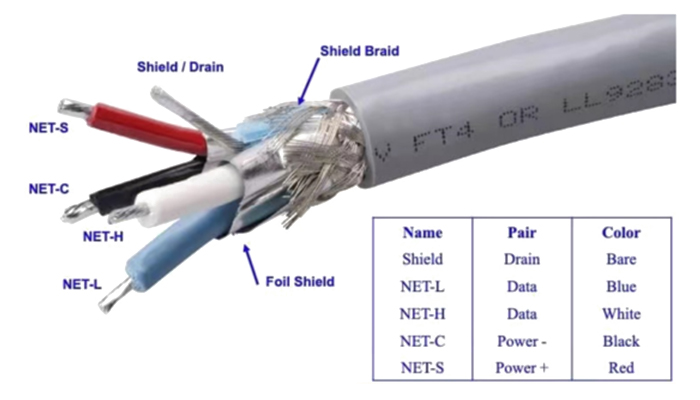
NMEA 2000 Cable Specifications
Power and Ground Wires (typically 22 AWG or 18 AWG)
Red Wire (V+): Supplies positive voltage (12V or 24V DC) to the network, powering all connected devices.
Black Wire (V- or GND): Serves as the ground connection for the network, ensuring electrical safety and stability.
Data Wires (typically 22 AWG or 16 AWG)
Blue Wire (CAN_H): Carries the high side of the CAN (Controller Area Network) data signal, enabling the transmission of data between devices.
White Wire (CAN_L): Carries the low side of the CAN data signal, completing the differential signaling necessary for reliable communication.
Shield
Shield/Braid: Provides protection against electromagnetic interference (EMI), ensuring data integrity and preventing signal degradation in the harsh marine environment.
Jacket
Marine-grade PVC or TPU: Ensures durability and environmental resistance, protecting the internal wires from physical damage, moisture, and UV exposure.
NMEA 2000 Backbone (Trunk) Cable
-
Network Spine: It carries the collective data and power for the entire system.
-
Scalability: You can extend the backbone by adding more T-connectors, provided you don't exceed the maximum cumulative length.
-
Critical Rule: An NMEA 2000 backbone must be terminated at both ends with a 120-ohm resistor (Terminator) to prevent signal reflection.
Trunk cables are the main communication paths that form the NMEA 2000 network, acting as the central line for all equipment and power connections. They can be much longer than branch cables, with a total allowable length of up to 200 metres (656 ft), which allows coverage of extensive networks on large vessels. Trunk cables connect T-connectors, which are used to connect equipment to the network, and run along the length of the vessel, forming the main structure and ensuring network coherence. The backbone cable extends the main line of the network, interconnecting all equipment and segments to maintain a coherent and reliable network.
NMEA 2000 Drop Cables
-
The 6-Meter Rule: The most important technical tip—no single drop cable can exceed 6 meters (20 feet). Exceeding this length causes signal timing issues and data loss.
-
Total Drop Limit: The sum of all drop cables in a network should not exceed 78 meters (256 feet).
-
Connection: It plugs into the "top" of a T-connector and runs directly to the device.
Branch cables connect individual devices (such as sensors, displays, and other electronic devices) to the trunk cable. They extend from the T-connectors on the backbone to each device, providing access to data and power. These cables are shorter than the trunk cables, with a maximum allowable length of 6 metres (20 feet), to ensure signal integrity and reduce the risk of data loss. Branch cables connect devices to the backbone, allowing them to communicate with the rest of the network. Each device requires a branch cable that connects to the backbone via T-connectors, enabling integrated operation of all connected devices.
Network Structure
- Backbone Cables: Imagine the backbone cables as the central spine of the network, running along the length of the boat and connecting various segments and T-connectors. This spine forms the foundation of the network, supporting all communication and power distribution.
- Drop Cables: Drop cables branch off from the backbone, connecting each individual device to the network. These cables ensure that every device can communicate with others via the backbone, maintaining the integrity and functionality of the network.

3 Golden Rules for NMEA 2000 Installation
To ensure your marine electronics perform flawlessly, follow these industry best practices:
-
Never Daisy-Chain: Never connect one device to another via drop cables. Every device must have its own T-connector on the backbone.
-
Monitor Voltage Drop: If your backbone is long (over 50m), place the Power-Pole (Yellow cable) in the center of the network to balance voltage distribution.
-
Check Your Terminators: Every network must have exactly two terminators—one at each far end of the backbone.
Contact Us
Choosing the right NMEA 2000 cables is about more than just length; it’s about maintaining the integrity of your boat’s "nervous system." Use heavy-duty Trunk cables for your main runs and keep your Drop cables short and direct.
- NMEA 2000 Connectors
- NMEA 2000 Cables
- NMEA 2000 Terminator Resistor
- NMEA 2000 Starter Kit
- NMEA 2000 Datasheets
As an industry specialist at Renhotec Group, I have years of expertise in the field of electronic interconnection. Founded in 2008, Renhotec Group is a global leader in designing and manufacturing connectors, cables, and custom electronic components for a wide range of industries. We are committed to providing high-performance interconnect solutions, leveraging technical innovation and rigorous quality standards to empower global customers across industrial, RF, and EV sectors.
I assume that the Yamaha outboard engine cable is also a DROP cable. But, is this cable also limited to 20 feet? I see several sellers offering longer Yamaha engine data cables. Am I missing something? I’d like to use a Yamaha engine data cable direct to the Simrad NSS EVO3 which requires about 27 feet. Do I have to extend the backbone to get within the 20 foot drop cable limitation? Would I be better off to extend the backbone all the way to the transom and use a short Yamaha data drop cable to connect?
Hi, Great question.
Yes, the Yamaha engine interface cable is generally considered a drop cable in an NMEA 2000 network, so the recommended maximum length is 6 meters (20 feet) per the NMEA 2000 standard. While some longer Yamaha engine cables are available and may work in certain installations, the best practice is still to keep the engine drop cable short and extend the backbone instead.
For your setup with the Simrad NSS EVO3, the recommended solution would be to extend the NMEA 2000 backbone closer to the transom, install a T-connector there, and then use a short Yamaha engine cable to connect the outboard.
This provides the most reliable network performance and follows standard NMEA 2000 network design practices.