


If you build cable for a living, USB comes up constantly. Some cables end up on mice and keyboards, some carry flash drives and portable SSDs, and others live inside equipment, moving data between boards.
From the outside, most USB cables look pretty much alike. Strip the jacket and you find the same thing: a handful of insulated conductors and a shield over them.
That is where the similarity gets interesting. USB 2.0 tops out at 480 Mbps. The first generation of USB 3.0 SuperSpeed already ran at 5 Gbps — more than ten times faster. Both are copper cables carrying data, so where does the gap actually come from?
The short answer
- Signaling rate. 480 Mbps for USB 2.0 High-Speed, 5 Gbps for the first USB 3.0 SuperSpeed generation.
- Conductors. Four in a typical USB 2.0 cable, eight in a USB 3.0 counterpart — the extra four form two SuperSpeed pairs.
- Duplexing. USB 2.0 shares one pair between transmit and receive. USB 3.0 gives each direction its own pair.
- The part that is easy to miss. Both standards specify roughly the same 90 Ω differential impedance. The 90 Ω number is not what makes USB 3.0 hard — the bandwidth behind it is.
- Where it really goes wrong. Not in the middle of the cable, but at the connector transition and the shield termination.
1. Before you look at the cable: what separates USB 2.0 from USB 3.0?
When we say “USB 2.0” or “USB 3.0,” we are talking about transfer standards, not connector shapes.
USB-A, USB-B, Mini-USB, Micro-USB and USB Type-C describe the connector. USB 2.0 and USB 3.0 describe the communication method and the capability behind it. The two are not interchangeable.
A Type-C cable may be wired for USB 2.0 data only, while another with an identical plug runs USB 3.x SuperSpeed. The plug tells you nothing about the speed.
So why is USB 3.0 so much faster? One key change: it no longer relies solely on the original data pair. It adds dedicated high-speed lanes.
On USB 2.0, D+ and D− carry data. In High-Speed mode, transmit and receive share that single pair — the link is half-duplex, so the two directions cannot run at the same time.
USB 3.0 keeps that channel and layers two SuperSpeed differential pairs on top: one for transmit, one for receive. Now both directions move simultaneously — a dual-simplex arrangement.
One caveat worth stating plainly: full duplex is only one of the improvements in USB 3.0, and it is not on its own the reason for a tenfold speed jump. The higher signaling rate, the new physical layer design, and the associated encoding scheme matter just as much.
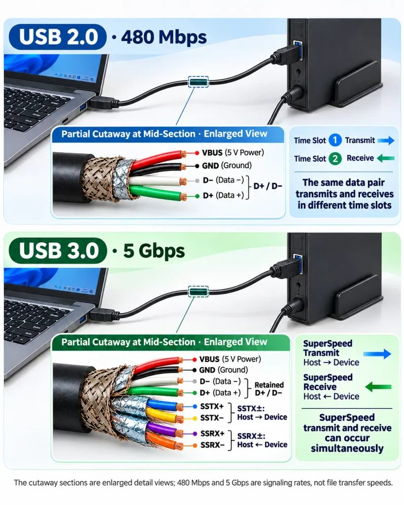
For those of us making the cable, though, the change that matters most is structural. Add a high-speed path, and the inside of the cable has to change with it.
2. Strip the jacket and the difference shows up
Let us stay with conventional USB-A and USB-B data cables and leave the Type-C construction out of this for now.
A typical USB 2.0 data cable carries four primary conductors:
- VBUS — the power rail
- GND — power return
- D+ — non-inverting data
- D− — inverting data
D+ and D− form a single differential pair that carries the data. USB 3.0 keeps all four and adds two high-speed differential pairs:
- SSTX+ / SSTX− — SuperSpeed transmit pair
- SSRX+ / SSRX− — SuperSpeed receive pair
Counting only the primary power and signal conductors, a typical USB 2.0 cable has four and a typical USB 3.0 cable has eight. Shields and drain wires fall outside that count, and real constructions vary with the standard, the connector type and the design.
So USB 3.0 is not simply a matter of swapping the two USB 2.0 data wires for better copper. The original channel stays; two pairs dedicated to high-speed traffic are added alongside it.
And that is not the end of the story. Adding two high-speed pairs only means the channels exist. It does not mean the cable will reliably hit 5 Gbps once the connections are made. That is precisely where cable design earns its keep.
3. Both specs say 90 Ω — so why is USB 3.0 harder on the cable?
Anyone working on high-speed cable runs into differential impedance sooner or later. USB 2.0 High-Speed and USB 3.0 SuperSpeed both call for a nominal differential impedance of around 90 Ω.
Which raises the question: if both are 90 Ω, why does USB 3.0 place visibly higher demands on cable quality?
First, a common misconception to clear up. USB 2.0 is not a standard where impedance can be ignored, and its cables are not free to be built any which way. The difference is that high-speed signaling is far less forgiving of the entire transmission path.
Think of differential impedance as an electrical property of the line. It depends on conductor spacing, the dielectric behavior of the insulation, conductor dimensions, and how the pair is constructed. As a signal travels along the cable, any abrupt change in impedance can produce reflections.
Say the cable itself is on spec, but inside the connector the conductors fan out and the solder joints change the geometry. The electrical environment the signal sees at that point is no longer continuous. It is like a well-paved road with a rough seam at the joint.
For a high-speed signal, that discontinuity produces stronger reflections and can throw off the receiver’s ability to resolve the data.
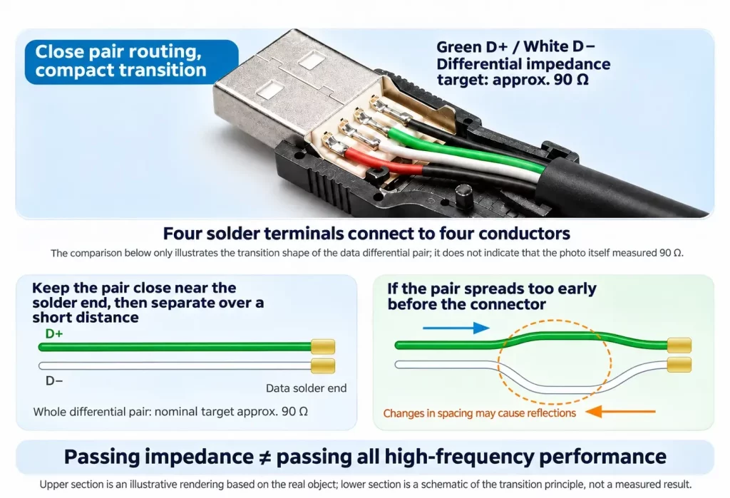
And passing impedance does not guarantee high-frequency performance. Impedance is one parameter among several. Insertion loss, return loss, crosstalk, and the transition between cable and connector all bear on the achievable data rate. So two cables that both measure close to 90 Ω are not thereby both capable of handling USB 3.0 SuperSpeed.
4. Why USB 3.0 cables care more about the high-speed pairs — and the shield
Look back at the construction and it becomes clear the two added pairs cannot just be any two wires spliced in.
A high-speed differential pair needs a controlled electrical geometry: conductor spacing, insulation, twist, and continuity along the whole run. If a pair separates somewhere along the way, or the two conductors become noticeably asymmetrical, the differential transmission characteristics break down and reflections and signal distortion increase.
Crosstalk between pairs has to be managed too. Signal on one pair can couple electromagnetically into its neighbor. Without enough isolation, or with a flawed physical design, the receiver simply gets a worse signal.
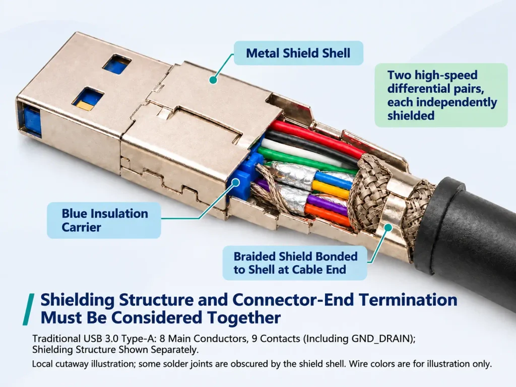
That is why USB 3.0 cables typically use tighter pair routing and more elaborate shielding. Cables built to the relevant standards may apply individual shields around the SuperSpeed pairs as well as an overall shield over the cable. The individual shield helps contain coupling between pairs and to the outside world; the overall shield helps control interference between the cable and its environment.
More shielding is not automatically better, though, and you cannot judge a cable by whether foil or braid is present. Whether the shield construction is appropriate, whether it is reliably terminated, and whether high-frequency continuity holds through the connector all have to be weighed against the design and the test results.
One more point that is easy to overlook: a compliant cable does not make a compliant assembly. From the point where the cable enters the connector — conductor routing, shield termination, solder geometry, the electrical transition inside the connector — each of these can degrade high-speed performance. Checking only the middle of the cable, or buzzing it out with a multimeter, tells you nothing about whether it will support high-speed transmission.
5. Why USB 2.0 is usually the easier one to run long
In practice, plenty of people find that a cable works fine at USB 2.0 lengths but turns unstable at USB 3.0 — more errors, or no SuperSpeed link at all. Does that mean USB 2.0 has looser cable requirements? Not really.
The more accurate statement is that the two standards signal at different rates, and therefore ask different things of the link. USB 2.0 High-Speed signals at 480 Mbps; first-generation USB 3.0 SuperSpeed signals at 5 Gbps. Raise the rate, and frequency-dependent loss, impedance discontinuities, crosstalk and connector transitions all take a larger toll on what arrives at the receiver.
Loss also accumulates with length. On a high-speed channel, excess loss eats directly into the margin available at the receiver — which is why a cable that behaves at USB 2.0 may not hold up at USB 3.0.
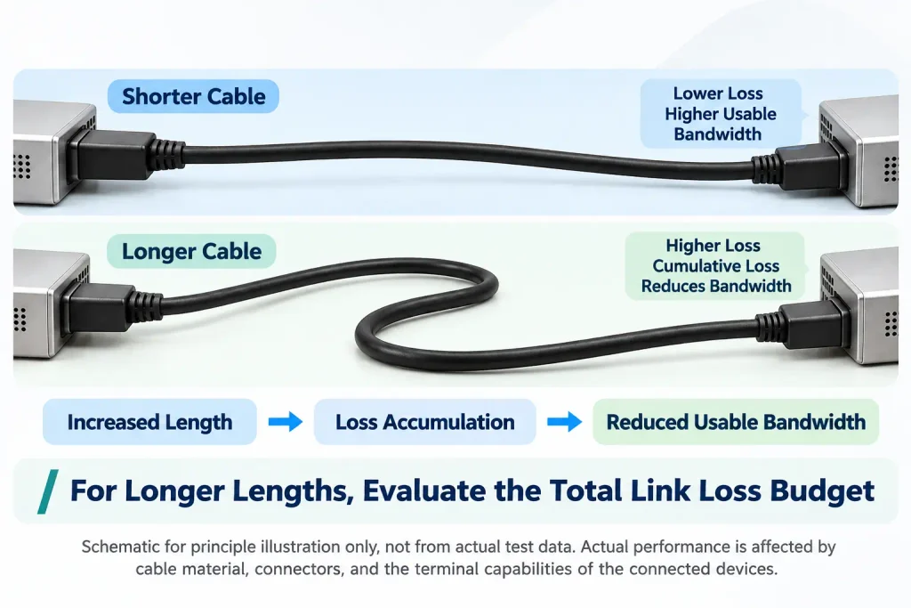
But to be clear: you cannot say flatly that USB 2.0 always reaches farther than USB 3.0. Usable length depends on the applicable standard, the cable design, conductor and insulation materials, connector performance, the signal capability of the devices at each end, and the loss budget of the whole link.
Cable length is never a standalone parameter. Designing a high-speed cable means asking whether the entire link can meet its signal-integrity requirements — not simply whether the conductors are thick enough.
6. USB 2.0 Cable vs USB 3.0 Cable
| USB 2.0 cable | USB 3.0 cable | |
|---|---|---|
| Typical maximum signaling rate | 480 Mbps | 5 Gbps |
| Primary signal channels | One D+/D− pair | D+/D− retained, plus two SuperSpeed pairs |
| Primary power and signal conductors | 4 | 8 |
| High-speed duplexing | Transmit and receive share one pair | Separate pairs for transmit and receive |
| Impedance | Differential impedance must be controlled | Same, plus full high-speed channel performance |
| Pair construction | Must meet the requirements of the applicable signal | Tighter control of SuperSpeed pair geometry and consistency |
| Shielding | Set by cable design and the applicable standard | Typically finer per-pair and overall shielding |
| Design priorities | Continuity, impedance, loss, compliance | Impedance, insertion loss, return loss, crosstalk, connector transition |
7. Where this actually bites: industrial camera links
Nowhere does the connector end matter more than in machine vision. A USB 3.0 industrial camera pushes 5 Gbps through a cable that gets flexed, dragged across a cable carrier and re-plugged on a production line — often several times a shift.
The failure modes are predictable, and all three land on the points this article has been circling:
- Retention. A plain Micro-B plug works itself loose under vibration. Every time it lifts, the electrical environment at the connector changes — the discontinuity from section 3, except now it is intermittent, which is worse to diagnose than a fixed defect.
- Strain relief. Cables rarely fail in the middle. They fail at the overmold, where a stiff boot concentrates bending stress on a few strands. A molded boot spreads that stress over a longer section.
- Routing space. Cameras sit inside tight enclosures. A right-angle or left-angle overmold removes the bend radius a straight plug would demand — and a bend radius is exactly what degrades the pair geometry near the connector.
This is the class of assembly Renhotec builds for industrial cameras: USB 3.0 Type-A cables with screw-lock Micro-B and Type-B connectors, molded strain relief, and angled overmolds where the enclosure leaves no room for a straight plug.


One note on picking a length: as section 5 explains, the loss budget is a property of the whole link. A shorter cable buys margin; a longer one eats it. If a 5 Gbps camera link is marginal on a long run, the first thing to try is a shorter, better-terminated assembly — not a thicker conductor.
Closing thoughts
Seen this way, the gap between USB 2.0 and USB 3.0 is not just a few extra conductors. USB 3.0 adds dedicated high-speed differential channels, and with them far stricter demands on construction, signal integrity and the connector transition.
From a cable-engineering perspective, conductor count is only the starting point. Pair geometry, impedance continuity, loss, crosstalk and shield termination all shape what the cable can actually do.
So when the question is whether a USB 3.0 cable will run at full speed, the answer is not in how many conductors it has, or whether it passes an impedance check. It is in whether the finished assembly meets the electrical performance requirements of the standard.
That is the genuinely interesting part of high-speed cable design: a few strands of copper on the outside, and an entire transmission link’s worth of detail deciding what they can deliver.